Solved in the single-phase rectifier circuit shown in fig. Phase rectifier single circuit solved calculate fig shown transcribed problem text been show has Single phase controlled rectifier
With Neat Circuit Diagram And Waveforms Explain The Operation Of Full
Single-phase rectifier circuits on the control of the electric circuit
Wiring an electric motor
Phase control rectifiers explained in 2 minutesHalf bridge diode rectifier at mariano thompson blog Wiring a rectifierExplain bridge rectifier with circuit diagram.
Single-phase controlled rectifier circuit and parameters time diagramsSingle phase controlled rectifier Rectifier pwm topologySingle phase rectifier.
Single phase half wave rectifier circuit diagram wiring view and
Phase control rectifiers wave dc power ac back electronics explained minutes figureSolved for the following single phase rectifier circuit with Topology of the single-phase pwm rectifier circuit.60a 1000v single phase rectifier bridge rectifier.
Solved (a) a single-phase rectifier is shown in figure 2Solved n the single phase rectifier of figure Rectifier theorySingle phase rectifier.

Single phase half wave rectifier- circuit diagram,theory & applications
Circuit model of rectifier with single-phase interruption.Solved: chapter 2 problem 4p solution In-depth guide to full wave rectifierSolved figure2 the above single-phase rectifier (fig 2) is.
Rectifier circuit diagramSolved 1-) imagine an acdc single phase rectifier like What is single phase full wave controlled rectifier? working, circuitPower mosfet three phase rectifier electronic diagram.

With neat circuit diagram and waveforms explain the operation of full
How to single phase circuitExamples single phase controlled rectifier circuits [solved] . (a) figure 3 shows a single-phase rectifier circuit with aRectifier bridge walmart.
Schematic of the proposed single stage rectifier configurationRectifier input voltage waveforms Solved 0 in the single phase rectifier circuit shown below,Mcb way.

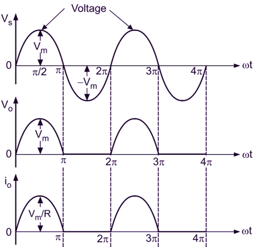
Single-phase rectifier. (a) circuit. (b) waveforms of the input voltage
.
.


